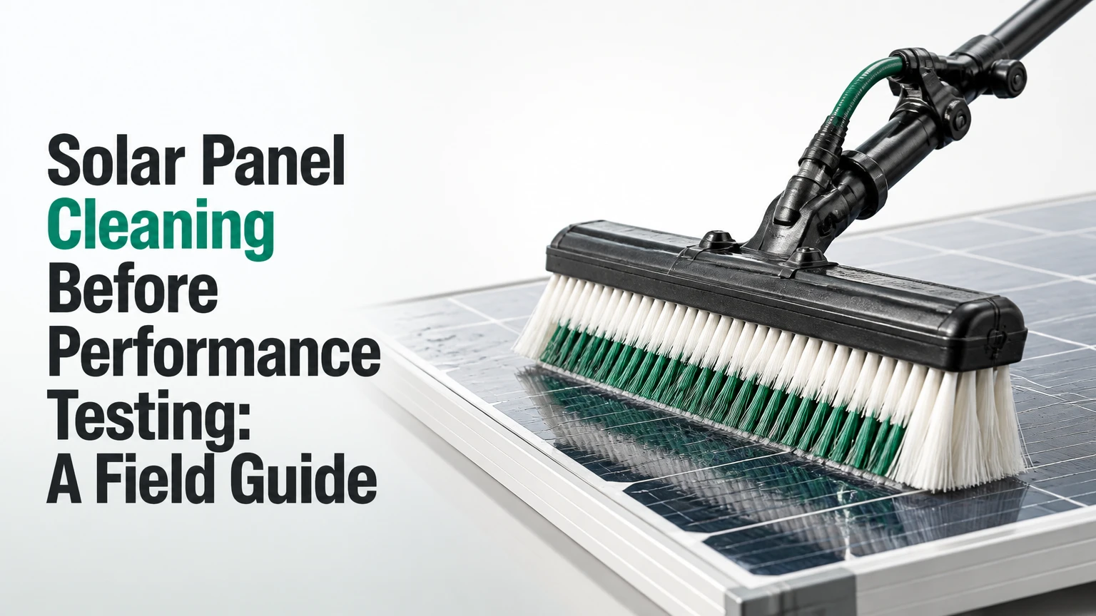
Solar panel cleaning before performance testing removes temporary surface soiling so measured power, efficiency, performance ratio, or I-V results represent the PV system rather than dust and residue. The correct process combines electrical isolation, dry debris removal, purified-water washing, careful inspection, and documented test conditions; cleaning alone does not recreate laboratory STC conditions.
Key Facts
Soiling can reduce irradiance reaching cells and create nonuniform mismatch across a module or string.
Disconnecting an array does not eliminate DC voltage while modules receive sunlight; qualified personnel must control electrical hazards.
RO or DI water is preferred where mineral deposits could remain, but the acceptable TDS and conductivity limit should follow the module and contractor specification.
Performance testing still requires measured irradiance, module temperature, wind conditions, and instrument calibration after cleaning.
A practical scheduling window is 24-48 hours before testing, unless rapid re-soiling makes same-day testing more representative.
The clean baseline should include cleaning time, water quality, weather, visual condition, and test configuration.
What does cleaning before a performance test accomplish?
Cleaning removes an uncontrolled optical variable from the module surface. Dust, ash, pollen, salt, bird droppings, mud, and industrial films absorb or scatter light, while a single opaque deposit can shade several cells and create local mismatch that a whole-array average cannot reveal.
The purpose is not to make the array produce its nameplate rating. A module’s nameplate is specified under Standard Test Conditions, normally 1,000 W/m² irradiance, 25°C cell temperature, and an AM1.5 spectrum. Field testing occurs under different conditions and must use appropriate temperature and irradiance corrections.
IEC 61724-1 provides a framework for PV system performance monitoring, including performance ratio and environmental measurements. IEC 60904-1 addresses I-V characteristic measurements for photovoltaic devices. Neither standard says that washing alone makes field data equivalent to an STC laboratory result.
A clean surface improves comparability. It does not remove degradation, wiring loss, inverter clipping, tracker error, temperature loss, spectral effects, or sensor bias.
Why dirty modules distort electrical data
A uniform dust layer generally lowers short-circuit current because less light reaches the cells. Bird droppings, leaf fragments, and streaks create a different problem: partial obstruction can produce uneven current among cells and bypass-diode sections.
The result may include:
- Lower measured maximum power, current, and energy yield
- Greater string-to-string variation
- False suspicion of module degradation
- Localized heating during operation
- An inaccurate soiling loss estimate
- A misleading performance ratio if reference irradiance is not representative
NREL’s photovoltaic soiling research treats deposited material as a measurable loss mechanism, not simply a cosmetic defect. The practical implication is straightforward: record the soiling condition and either clean all test units or deliberately measure soiling as part of the test design.
When should panels be cleaned before testing?
Clean panels 24-48 hours before a planned audit when the site has moderate dust, stable weather, and low re-soiling risk. Test sooner, often within a few hours, when windblown dust, agricultural activity, wildfire smoke, sea salt, or nearby construction can materially change the surface condition.
Early morning is often safer because module temperatures and wind speeds are lower, but the test itself may require a defined irradiance window. Cleaning at dawn and testing at noon can leave enough time for new dust, pollen, or bird contamination.
Do not clean solely because the panels look slightly dusty. First estimate whether the contamination is large enough to affect the stated test uncertainty. A contract acceptance test with a tight guarantee requires stronger control than a routine troubleshooting visit.
| Situation | Preferred cleaning-to-test interval | Reason |
|---|---|---|
| Indoor-like roof, low dust, stable weather | 24-48 hours | Limits disruption while preserving a clean reference |
| Utility site beside an unpaved road | 2-8 hours | Wind can recreate measurable soiling quickly |
| Coastal array with salt aerosol | Same day | Hygroscopic residue can reform after washing |
| Agricultural or harvest season | Same morning | Dust events can occur during the workday |
| Rain forecast before testing | After rain, then inspect | Rain may redistribute soil rather than remove it |
| Contractual acceptance test | Per contract, commonly 24 hours or less | Preserves chain of custody and agreed conditions |
When is cleaning the wrong decision?
Postpone cleaning during lightning, high winds, freezing conditions, heavy rain, or unsafe roof access. Do not wash modules with cracked glass, loose frames, exposed conductors, damaged connectors, or visibly compromised junction boxes until a qualified technician evaluates them.
A clean surface can also be the wrong test objective. If the owner wants operational performance under normal site conditions, a soiling-control measurement may be more useful than a fully washed baseline. The test plan must state whether the result represents clean performance, as-found performance, or recoverable soiling loss.
How do you clean panels before performance testing?
Use a controlled six-step process: inspect and establish a safe work zone, remove dry abrasive debris, verify water quality, wash with approved equipment, rinse and dry without scratching the glass, then document the finished array before testing. The technician must preserve the test configuration and record the exact cleaning completion time.
Before you start
| Requirement | Typical field value | Verification |
|---|---|---|
| Crew time, residential 10 kW | 1-3 hours | Include setup and inspection |
| Crew time, 1 MW block | 4-12 labor-hours | Varies with row access and terrain |
| Purified water | 0.5-2 L per module | Depends on soil load and equipment |
| Water quality target | Site specification, often below 75 ppm TDS | Measure at the brush or nozzle |
| Washing pressure | Low pressure, commonly below 35-50 psi at nozzle | Confirm with a gauge |
| Test instruments | Calibrated irradiance sensor, temperature sensors, I-V tracer or power meter | Check calibration dates |
| Safety prerequisites | Competent electrical and working-at-height personnel | Complete site permit and risk assessment |
The 75 ppm TDS value is a useful operational target, not a universal legal limit. Conductivity, module coating, drying method, and local mineral chemistry matter more than a single number. A supplier may specify a lower value, and high-purity water can still leave marks if dirty runoff dries on the glass.
Step 1: Inspect and isolate the array
Walk the array perimeter and inspect module glass, frames, clamps, cables, connectors, junction boxes, drainage paths, and roof or tracker access. Photograph defects before water reaches them.
Apply the site’s lockout and tagout procedure to AC and DC equipment where appropriate, and verify the work state with approved instruments. Disconnects reduce circuit accessibility, but sunlight can keep module and string conductors energized. Never treat an open switch as proof that all DC voltage is absent.
Success checkpoint: The work permit identifies the array block, test boundary, access route, and responsible electrical authority.
Common mistake: Washing first and reporting a pre-existing ground fault as a cleaning-related failure.
Step 2: Remove loose dry debris
Use a clean, soft, nonabrasive brush or air method approved by the module manufacturer to remove sand, gravel, leaves, and loose dust. Dry removal matters because dragging dry grit across wet glass can create scratches and haze.
Do not use hard bristles, metal tools, abrasive pads, or improvised roof brooms. Anti-static claims are less important than bristle softness, cleanliness, and the absence of trapped grit.
Success checkpoint: No loose particles remain that could be dragged across the anti-reflective coating during washing.
Common mistake: Applying water to a thick layer of dry sand, which turns loose mineral particles into an abrasive slurry.
Step 3: Verify water and equipment
Measure TDS or conductivity at the point of use, not only at the tank. RO systems reduce dissolved minerals, while DI resin removes remaining ions; exhausted resin can produce apparently clear water that dries into white scale.
Use a manufacturer-approved soft brush, water-fed pole, or automated cleaning head. Inspect hose fittings, squeegee edges, brush faces, and filters for embedded grit. A pressure washer is acceptable only when the equipment manufacturer and module supplier permit it, with a wide spray pattern and low delivery pressure.
Success checkpoint: The water reading, equipment condition, and module cleaning specification are written into the job record.
Common mistake: Reporting pump pressure instead of nozzle pressure. A high-pressure pump can still deliver low pressure through a regulated, wide-angle head, while a small nozzle can create damaging local force.
Step 4: Wash in controlled sections
Work from the upper row toward the lower row, or follow the module manufacturer’s drainage instructions, so runoff does not contaminate finished surfaces. Wet a manageable section, agitate adhered soil with a soft brush, and keep the brush moving without forcing it against the glass.
Avoid washing hot glass with very cold water. A fixed universal temperature delta, such as 20°C, cannot guarantee safety because glass condition, water volume, flow rate, and manufacturer limits also affect thermal stress. Cool the work area or wash during lower-temperature periods instead.
Keep water away from open connectors, damaged junction boxes, cable entries, and inverter ventilation openings. Never flood the back of modules or direct jets at seals.
Success checkpoint: The surface has no visible film, bird-dropping residue, mud, or cleaning-line deposits under oblique light.
Common mistake: Scrubbing a stubborn deposit aggressively. Soften it with approved water and repeated gentle passes, then escalate to the supplier-approved method.
Step 5: Rinse and remove remaining droplets
Rinse with purified water until runoff is free of visible dirt and surfactant. A squeegee can reduce spotting in mineral-prone areas, but the rubber edge must be clean, intact, and free of grit; dragging a dirty blade can score the coating.
Some module manufacturers prohibit squeegees or recommend air drying. Follow the product manual over a generic cleaning practice.
Success checkpoint: The glass dries without white scale, streaks, detergent film, or isolated dirty corners.
Common mistake: Using household glass cleaner or dish soap. Residue can alter surface wetting, attract dust, and complicate a clean-baseline comparison.
Step 6: Inspect, restore, and release for testing
Reinspect the array after drying. Check for missed contamination, water marks, displaced cable clips, wet connectors, damaged seals, and changes to tracker or row access. Restore equipment only under the site’s electrical procedure, then confirm inverter status and alarms.
Record the cleaning completion timestamp, block or string identity, water reading, weather, personnel, equipment, photographs, and any excluded modules. Give the testing engineer the same information before measurement begins.
Success checkpoint: The tested boundary is clean, visually accepted, electrically normal, and traceable to a documented cleaning event.
Common mistake: Starting the performance test without recording which blocks were cleaned. That destroys the comparison between cleaned and uncleaned data.
What water, pressure, and brushes are appropriate?
Purified water, soft module-approved brushes, and low-pressure distribution are the normal choices for pre-test cleaning. There is no universal pressure, bristle diameter, TDS, or temperature-difference limit that overrides the module manufacturer’s instructions and the cleaning equipment design.
| Parameter | Practical control | Why it matters |
|---|---|---|
| TDS | Often below 75 ppm at point of use | Reduces mineral spotting during drying |
| Conductivity | Frequently below 100 µS/cm, if specified | Indicates ionic content more directly than appearance |
| Nozzle pressure | Commonly below 35-50 psi | Limits seal, coating, and edge-loading risk |
| Brush material | Soft nylon, polyester, or approved microfiber | Reduces abrasion when clean and grit-free |
| Water temperature | Close to module temperature | Reduces rapid thermal stress |
| Cleaning chemistry | Usually none unless manufacturer approves it | Prevents residue and coating interaction |
The AI Overview’s claim that pump pressure should never exceed 1,500 psi is not a useful general rule. Pump-source pressure does not describe the force delivered at the module, and a high-pressure source may be regulated before the nozzle. The relevant controls are nozzle pressure, spray geometry, standoff distance, flow, and supplier approval.
No generic brush diameter or ISO 21546 requirement should be treated as a universal PV cleaning specification. Ask the module manufacturer for approved materials and document the actual tool used.
Which cleaning method fits the site?
Manual water-fed cleaning is usually the best choice for residential systems, damaged areas, complex roof geometry, and small commercial arrays. Robotic dry or wet cleaning becomes more attractive for repetitive utility rows, while vehicle-mounted systems require stable ground access and adequate row clearance.
| Method | Typical scale | Typical cost | Main constraint |
|---|---|---|---|
| Manual water-fed pole | 1 kW-1 MW | $3-$7 per module | Labor, roof access, variable pace |
| Vehicle-mounted brush | 1-100 MW | $1-$2.50 per module | Flat terrain and collision clearance |
| Autonomous wet robot | 5-100 MW | $0.20-$0.80 per module per cycle | Capital cost and row compatibility |
| Autonomous dry robot | 5-100 MW | $0.002-$0.008 per watt, typical asset-dependent range | Fine dust control and maintenance |
The figures are typical planning ranges, not bids. Mobilization, water hauling, traffic control, insurance, access, row spacing, and local wages can change the price substantially.
Manual cleaning provides the most control around obstructions but creates more worker exposure and consistency risk. Vehicle systems clean quickly but can damage tracker components or rack structures if clearance sensing fails. Robots reduce repeated labor in compatible arrays, although their brushes, wheels, tracks, and alignment systems require inspection.
What does cleaning cost and how long does it take?
A residential 10 kW array commonly requires 1-3 labor-hours and roughly $150-$500 when access is straightforward. A utility-scale block may require 1-8 hours of operational downtime, depending on row access, water logistics, test boundaries, and whether cleaning occurs during non-generating hours.
| Installation | Cleaning approach | Typical duration | Typical planning cost |
|---|---|---|---|
| 5 kW roof array | Water-fed pole | 1-2 hours | $120-$300 |
| 100 kW C&I roof | Two-person manual crew | 3-8 hours | $500-$1,500 |
| 1 MW fixed-tilt block | Vehicle or manual crew | 4-12 hours | $1,000-$4,000 |
| 20 MW utility block | Robotic or mechanized cycle | 1-3 days by blocks | Site-specific contract |
Testing labor is separate. Cleaning immediately before a contractual test may reduce data uncertainty but can increase schedule risk if wet connectors, alarms, or re-soiling delay the measurement window.
How should the clean baseline be tested?
The testing engineer should define the test method before cleaning, then hold the array boundary and measurement procedure constant afterward. I-V curve tracing, inverter efficiency testing, capacity testing, and PR monitoring require different data and acceptance rules.
For I-V testing, record irradiance in the plane of array, module or backsheet temperature, wind, tracer settings, string identity, and instrument calibration. For performance ratio, use the project’s reference irradiance, temperature, availability, and energy conventions; cleaning is one controlled input, not the whole calculation.
A useful field design includes a cleaned sample block and, where contractually allowed, an uncleaned soiling reference. The difference provides evidence of recoverable soiling loss and prevents the clean baseline from being mistaken for normal operating performance.
What should the test record contain?
| Record item | Minimum entry | Example |
|---|---|---|
| Array identity | Site, block, inverter, string | North block, INV-04, strings 1-12 |
| Cleaning event | Date and completion time | 2026-04-12, 08:40 |
| Water quality | TDS or conductivity at nozzle | 18 ppm TDS |
| Conditions | Irradiance, temperature, wind | 850 W/m², 31°C, 3 m/s |
| Surface result | Photos and acceptance status | No scale, residue, or bird droppings |
| Electrical state | Alarms, insulation, configuration | No alarm, test boundary unchanged |
| Test method | Standard, instrument, settings | IEC 60904-1, calibrated I-V tracer |
The timestamp is especially important. If a wind event occurs between cleaning and measurement, the record allows the engineer to decide whether the clean condition remains valid.
What problems occur after washing?
Post-cleaning problems usually arise from three sources: mineral residue, mechanical abrasion, or water entering electrical components. Stop work when a fault appears, preserve the evidence, and diagnose the affected circuit before repeating the test.
| Symptom | Likely cause | Corrective action |
|---|---|---|
| White spots or haze | High-mineral rinse or exhausted DI resin | Recheck TDS, replace resin, rewash |
| Parallel streaks | Dirty or damaged squeegee edge | Flush surface and replace blade |
| Lower output after cleaning | Wet connector, alarm, or changed test conditions | Isolate circuit and inspect electrically |
| Inverter ground fault | Moisture or damaged insulation | Qualified insulation-resistance diagnosis |
| New fine scratches | Grit in brush or dragged debris | Photograph, stop cleaning, notify owner |
| Uneven clean appearance | Runoff, missed corners, or blocked drainage | Rewash section and verify under angled light |
A ground-fault alarm is not repaired by applying silicone casually. Qualified personnel should isolate the circuit, follow the inverter manufacturer’s diagnostic process, and perform insulation-resistance testing at the correct voltage and configuration. Connectors should be replaced or resealed only under the component manufacturer’s instructions.
Can rain replace a controlled cleaning?
Rain cannot reliably replace pre-test cleaning because rainfall intensity, wind, droplet chemistry, and runoff paths vary. Rain may remove loose dust while leaving bird droppings, oily films, salt, or dirt concentrated along the lower frame.
After rain, inspect the glass under angled light and compare representative modules across the test boundary. If deposits remain or the contract defines a clean condition, perform controlled cleaning rather than accepting rainfall as evidence.
What changes for different installation sizes?
Residential owners should avoid roof climbing and use a qualified contractor when access, fall protection, or electrical condition is uncertain. C&I managers should coordinate cleaning with production schedules and testing personnel. Utility operators should clean by test block, because cleaning an entire site can erase the ability to compare blocks under equivalent conditions.
For systems below 10 kW, a ground-operated water-fed pole and DI cartridge are usually adequate. For 10 kW-1 MW, a documented contractor process, water-quality log, and block-level photos provide better control. Above 1 MW, row geometry, tracker position, robot compatibility, water supply, and test sequencing dominate the decision.
Dry robotic cleaning may suit arid sites with loose dust, but it is not a universal replacement for wet washing. Sticky pollen, bird droppings, cement dust, and salt deposits often require water and manual spot treatment.
Common mistakes and how to prevent them
- Assuming disconnects remove all DC voltage. Modules generate voltage in daylight. Use qualified personnel, insulated procedures, and verified work controls.
- Washing during peak heat with cold water. Schedule cooler conditions and follow the manufacturer’s thermal guidance.
- Using untreated hard water. Measure at the outlet and rewash any mineral residue before testing.
- Scrubbing abrasive grit into the glass. Dry-remove sand first, then inspect brush cleanliness between sections.
- Cleaning only visibly dirty modules. Partial cleaning creates a mixed dataset unless the test deliberately uses a sample design.
- Treating a clean surface as proof of healthy equipment. Cleaning cannot correct degradation, mismatch, connector resistance, inverter faults, or sensor error.
A counterintuitive field rule is that a visually clean module can still produce poor test data if the irradiance sensor is dirty or misaligned. The reference sensor and temperature sensors need the same inspection discipline as the PV glass.
Another practitioner rule is to test a small representative section after cleaning before committing the entire site to a full audit. That pilot can reveal residue, unexpected alarms, or a mismatch between the cleaning method and the test specification.
FAQ
Does cleaning increase solar panel efficiency?
Cleaning can recover output lost to surface soiling, but it does not increase the module’s inherent conversion efficiency above its design capability. The measured gain depends on the type, thickness, distribution, and optical properties of the deposits, as well as irradiance and temperature during the comparison.
Should panels be cleaned before an I-V curve test?
Panels should be cleaned before an I-V test when the objective is to measure electrical condition under a controlled clean-surface state. The test plan should record irradiance, module temperature, instrument settings, and any excluded modules, because cleaning alone cannot normalize field conditions to STC.
How pure should water be for solar panel washing?
Water should be pure enough to dry without mineral scale under the module supplier’s cleaning specification. Many field crews target below 75 ppm TDS, while conductivity below 100 µS/cm is a common operational reference, but the point-of-use reading and the finished surface matter more than an arbitrary universal threshold.
Can pressure washing damage photovoltaic modules?
Pressure washing can damage glass coatings, seals, frames, connectors, and junction boxes when pressure, nozzle geometry, or distance is unsuitable. Use a wide, low-pressure application only when approved by the module manufacturer, and never direct a concentrated jet at edges, seals, cables, or electrical enclosures.
Is it better to test immediately after cleaning?
Immediate testing is best when rapid re-soiling is likely and the surface has fully drained and dried. Otherwise, testing within 24-48 hours can provide a practical clean baseline, provided the operator records weather, re-soiling evidence, and the exact interval between cleaning and measurement.
What if output remains low after the panels are clean?
Check irradiance sensor accuracy, module temperature, inverter operating limits, string current, connector resistance, insulation status, shading, tracker position, and test configuration. Persistent low output after cleaning indicates that soiling was not the only loss mechanism and requires electrical or performance diagnostics.
The Bottom Line
Solar panel cleaning before performance testing should produce a documented, repeatable surface condition, not merely a visibly brighter array. Use qualified electrical controls, dry-remove abrasive debris, apply approved low-pressure washing with measured water quality, inspect for residue and water intrusion, and preserve the test boundary.
Schedule cleaning close enough to the test to limit re-soiling, but allow the array to dry and the crew to complete post-cleaning checks. Record the timestamp, TDS or conductivity, weather, photographs, equipment, and test conditions. That evidence turns cleaning from a cosmetic maintenance task into a defensible part of PV performance measurement.